Transferring Entities between floor plans
LEGION Model Builder represents space in two dimensions. However, more often than not, multiple level venues have different floors which overlap when viewed in plan. To get the best visual outputs, it is necessary to rearrange the CAD into separate floor plans with a single CAD layout (file) such that the different floor levels do not overlap. In cases where different floor levels do not overlap in plan view, it is not necessary to split the CAD into different levels.
The initial task of creating multiple levels within a LEGION model involves arranging the respective floor plans during the CAD preparation stage, as illustrated in the model-ready plan of the three-level office building shown below.
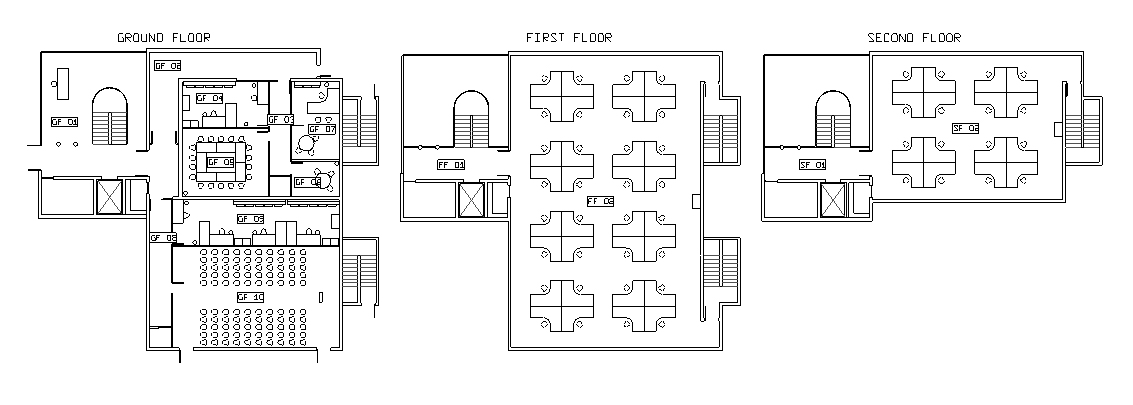
Movement between floor-levels is then achieved by an instantaneous transfer of Entities from one floor plan to another via Stairs, Escalators, or Level Exits/Level Entrance pairs (these objects are discussed in detail in Spatial Objects In Detail).
Creating multiple levels is initially a CAD task until the Entity movement between levels is introduced. Consider the plan of a football stand below.
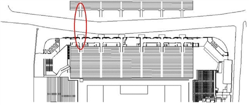
The back of the stand appears to lie behind the road bordering the stadium grounds. In reality, the rear section of the stand is directly above the ground-level concourse, which is also an area of interest for the model. The two levels have been arranged this way for visual purposes.
In terms of modelling, Entities are transferred from one level to another either by Stairs, Escalators, or Level Exit/Level Entrance pairs. Level Exits and Level Entrances are used here to describe the technique but Stairs and Escalators have built-in Level Exit/Level Entrance pairs which are not visible but accomplish the task in a similar manner.
The area circled in red above is shown in detail here. The red boxes are Level Exits and replicate the identical locations represented in the model by the green boxes (Level Entrances) in the lower part of the stand. These reflect the link between the upper and lower levels of the stand.
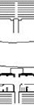
In a simulation of an evacuation of the stand, Entities leaving the back of the stand by the red Level Exits would instantaneously re-appear in the identically sized Level Entrances, in the same relative positions they were in on the upper level when they were transferred. This facilitates a seamless transfer between the two levels.
Similarly, when using Stairs or Escalators to transfer people between two levels, a transition area (or ‘overlap’) is specified for both the lower and upper components of the Stair or Escalator. This overlap area acts as the equivalent of a Level Exit/Level Entrance pair and must cover an area common to both levels.This is how the software replicates the movement of pedestrians between different levels in a two-dimensional model. As a consequence, the CAD representing the transfer area must be included in each related floor plan.
To preserve the integrity of the transfer of Entities from one level to the next, it is important that these transfer areas are identical in size and reflect the exact same location in space on both levels. To help achieve this, it is useful when re-arranging the CAD to place guidelines (in a presentation-only CAD layer) to indicate the transfer areas common to both levels.